How to Make a Grid Bias Battery
Background
Battery powered radios from the nineteen twenties and thirties usually required some form of grid bias battery, typically one with tappings at one and a half volt intervals up to nine volts. Much that several of these batteries still survive, some in reasonable cosmetic condition and others looking the worse for wear, seldom does one find a specimen in operational condition; and worse, they are now obsolete. Consequently, those of us interested in restoring old radios have either to make up a variable negative dc power supply, say, using an LM337 or similar IC regulator as part of a ‘battery eliminator’ or use a string of AA/AAA cells to supply the negative grid bias voltage. For years, I made do with the battery eliminator option since construction is simple and the current required is negligible (with any luck). Yet, wouldn’t it be nice to use the real thing since there’s usually space provided inside old radios for such a battery and it simplifies external wiring? Added to that, the battery design typically adds a nostalgic and decorative flourish to the wireless outfit. For this reason, I decided to embark on a little adventure to try to make such a battery and to make it look as authentic as possible. In the following paragraphs, you'll see how it turned out.
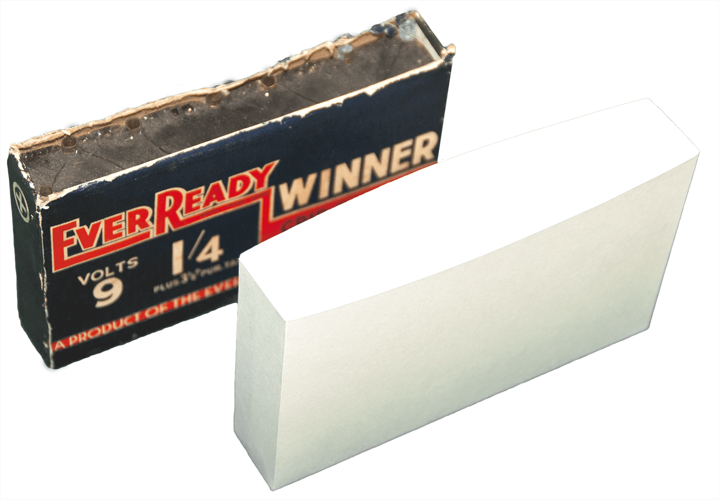
I was lucky to have at hand a couple of old grid bias batteries that I have had for more than forty years now, see photo below.
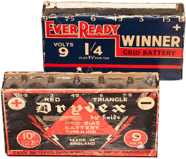
Both are in reasonable physical condition, though one has faded badly on one side. I decided to use these as masters to make new artwork, because I wanted to retain the original fonts. The samples were also useful for physical dimensions and the spacing of the tappings.
Secondly, I had to decide what modern cells would be best suited to use instead of the original ones. Much that the original batteries used cells of slightly greater size and capacity than AA cells, very few old TRF radios employed circuits that required grid current, so the capacity of the cells is almost irrelevant given that no current is drawn in theory. I decided to use AA cells in preference to AAA ones because the cost is similar and there’s adequate space available for AA cells if the wiring is soldered directly to the cell contacts. (Battery holders can be used, but they were a very tight fit because the flying leads added about a milli-metre to each end of the holder.) I found that thin hook-up wire could easily be soldered to the top cap and steel negative pole if both were roughened up with a fine grade file. I tried using wet/dry emery paper of about 220 grit, but it was much more difficult to wet the contact poles with solder, so I recommend using a small file. Whether tack soldering detracts from the life of the cell is unknown to me, but since my grid-bias battery is intended for the user to replace any/all of the cells, then it really doesn’t matter too much.
The design consists basically of four parts:
- Plastic AA cell box
- Connector strip
- Paper/card container
- Printed artwork
Plastic battery box
The outside dimensions are 4.850” x 2.30” x 0.85”. I used a removable side so that the AA cells and wiring could be easily manoeuvred during assembly. Since the bottom of the box acts as a ledge to support this removable side, I didn’t use anything to attach the side to the rest of the box since the paper/card container holds it in place when assembled.
I made several types of box, but ended up using some scrap acrylic that I purchased cheaply at a local plastics supplier. The sides and base were made from 0.062” thick plastic and the two end pieces were made from 0.25” thick plastic. I used a special squeeze bottle and needle delivery system for the acrylic cement (which seemed even less viscous than gasoline and seeps through whatever it touches), but even then more liquid came out than I had bargained for, or was required, so I had to clean up a few surfaces afterwards with 400, 600 and then 1000 grit wet/dry in order to make the box acceptable to my standard even though it is hidden inside the paper/card container. I put all this down to my total lack of experience with welding acrylic plastic, so expect a few mistakes if you’re a beginner like me. I recommend using latex/nitrile gloves when ‘gluing’ acrylic and don’t forget safety glasses. I also did the acrylic welds outside in fresh air although for the small amount of cement required, I didn’t smell any of the solvent.
Connector strip
The connector strip is the most difficult part to fabricate since it has to look good as it forms the top of the battery and it also has to secure the brass tappings securely. I used quarter inch thick plywood for my first attempt, but used quarter inch thick maple for the second because maple doesn’t split or chip when being drilled. I would imagine that good quality hardboard or medium density fibre-board (MDF) would serve just as well, but I have lots of off-cuts of maple left over from a kitchen cabinet project and I found it to be wonderfully strong and stable. For my latest connector strip, I made a silicone RTV mould and cast the connector strip, complete with holes, from two-part polyurethane resin. This resin is very easy to work with, sets very quickly and makes a rigid, stable connector strip with very little bowing. The only minor problem I had was in painting the strip afterwards, since the resin sets typically with an ivory colour and painting it was easier said than done, since the paint I used tended to ‘bead’ because of the high surface gloss of the moulded part. In some future model, I’ll push the boat out and spend some money on buying black polyurethane resin to see how it fares.
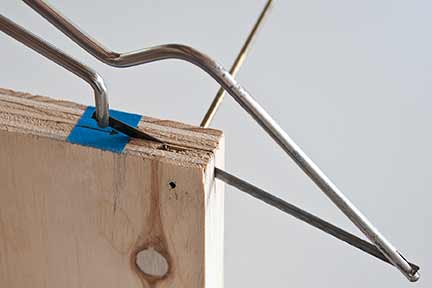
The next task was to make the brass tappings. For these, I used 5/32” outside diameter brass tubing, which is available from craft and hobby shops. For those using metric dimensions, it equates to 4 mm. tubing. This tubing is just the right size to accept the old-fashioned wander plugs, which were used extensively on old battery wireless sets. It isn’t quite as authentic as the original tappings made from formed thin brass strip, but is certainly easier to make and more durable in use. Each tapping is made from a half-inch length of the tubing, seven little tubes being required. (With the moulded connector strip, 10 mm. lengths would be more suitable.) I found the easiest way to make these was to construct a rudimentary sawing jig from a piece of scrap one inch thick plywood. This is shown in the following figure. It’s nothing more than a 5/32” hole drilled through the plywood with a slot cut across the hole with a hack-saw.
Just feed the tube in one side by tapping it gently with a small hammer with the jig placed flat on to another piece of scrap flat wood so that the end of the tube is flush with the side of the jig. I found that using a hole in the jig with the same diameter as the tube gave me an ‘extra hand’ in that it gripped the tube effectively. Then, cut the tube with the hack-saw and use the long length of the tubing to knock the half-inch piece out of the other side using gentle taps with the hammer. Repeat this action until you have seven half-inch lengths. The ends of the small pieces will probably have a few sharp burrs on them, so use some emery paper or a flat file to round them off. (The tubing I bought was of the half-hard variety and is difficult to cut once the hack-saw is part way through. Perhaps a Dremel type tool with a diamond saw attachment would do a better job, so that’s something for a future project.) I soaked all seven tappings in household ammonia for an hour or two to brighten up both outside and inside. It cleans them up nicely so that you can add a spot of solder to the inside later.
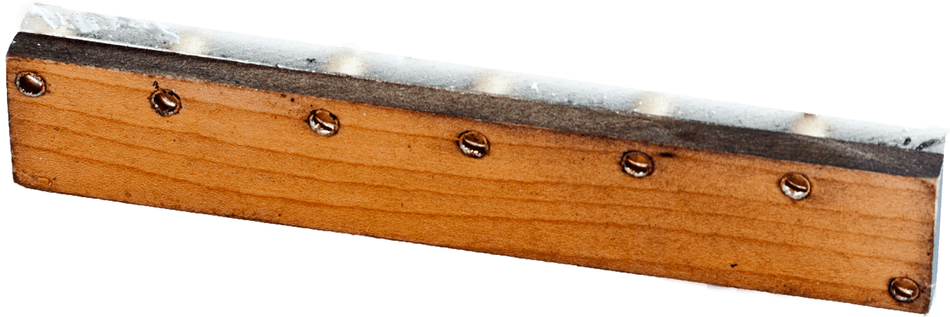
Drill seven holes in the wood for the connector strip roughly in line with the taps on the artwork. I say this because the tappings on both of my original batteries are not exactly equi-spaced. I put this down to early assembly techniques. Note that the positive tap is on one side and the other six negative taps are on the opposite edge. I spaced the hole centres one eighth of an inch in from the side of the wood. This is slightly more than on the originals, but it makes for easier drilling to avoid the hole spilling over the side. Sand off any rough edges and then spray the top side of the wood with a coat of matte black paint. Once completely dry, carefully tap the seven pieces of brass tubing into the wood so that they are flush with the unpainted side of the wood. At this point, I soldered a small blob of solder on each one to be used later to connect the wiring to the underside.
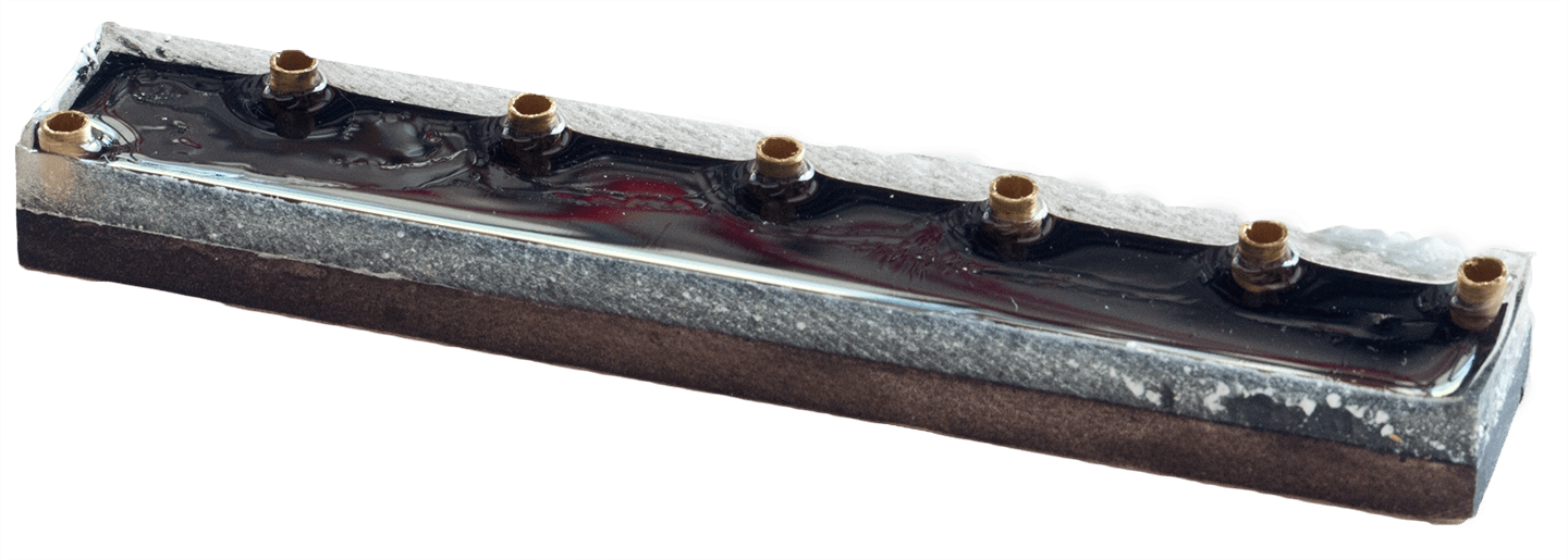
The dimensions of the wooden connector strip are 4.85 x 0.85 x 0.25 inches. The next operation is to simulate the pitch which was used on the original batteries. I used clear epoxy resin, the type used for casting small objects for ornaments. I believe polyester resin would work just as well, but I haven’t tried this. On my first attempt, I made a complete mess of this operation since I surrounded the wooden connector strip with card and masking tape, but the epoxy resin was not very viscous at the start and so it ran/penetrated right through the masking tape on to a melamine bench surface underneath. What a mess! After that fiasco, I made a simple mould from silicone RTV material. This is shown below with the connector strip inside.
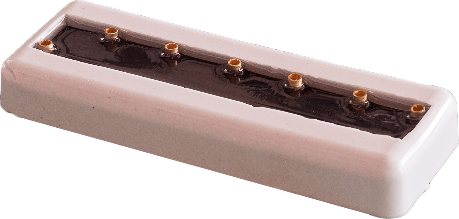
The connector strip sits at the bottom of the mould and you just pour in some epoxy resin, just enough to get a coating of about 1 – 2 mm. The black paint will show through the epoxy resin and the result looks very much like the original pitch. I’m sure other solutions will work equally well, but the epoxy resin, when cured, also acts to hold the connector taps very firmly in place.
Assembly
Once the connector strip is completed, solder the AA cell wiring from one cell to the next so they form a daisy chain. Make sure you also solder a short piece of wire to the top of each cell for soldering to the connector strip. You can see how I did the wiring here.
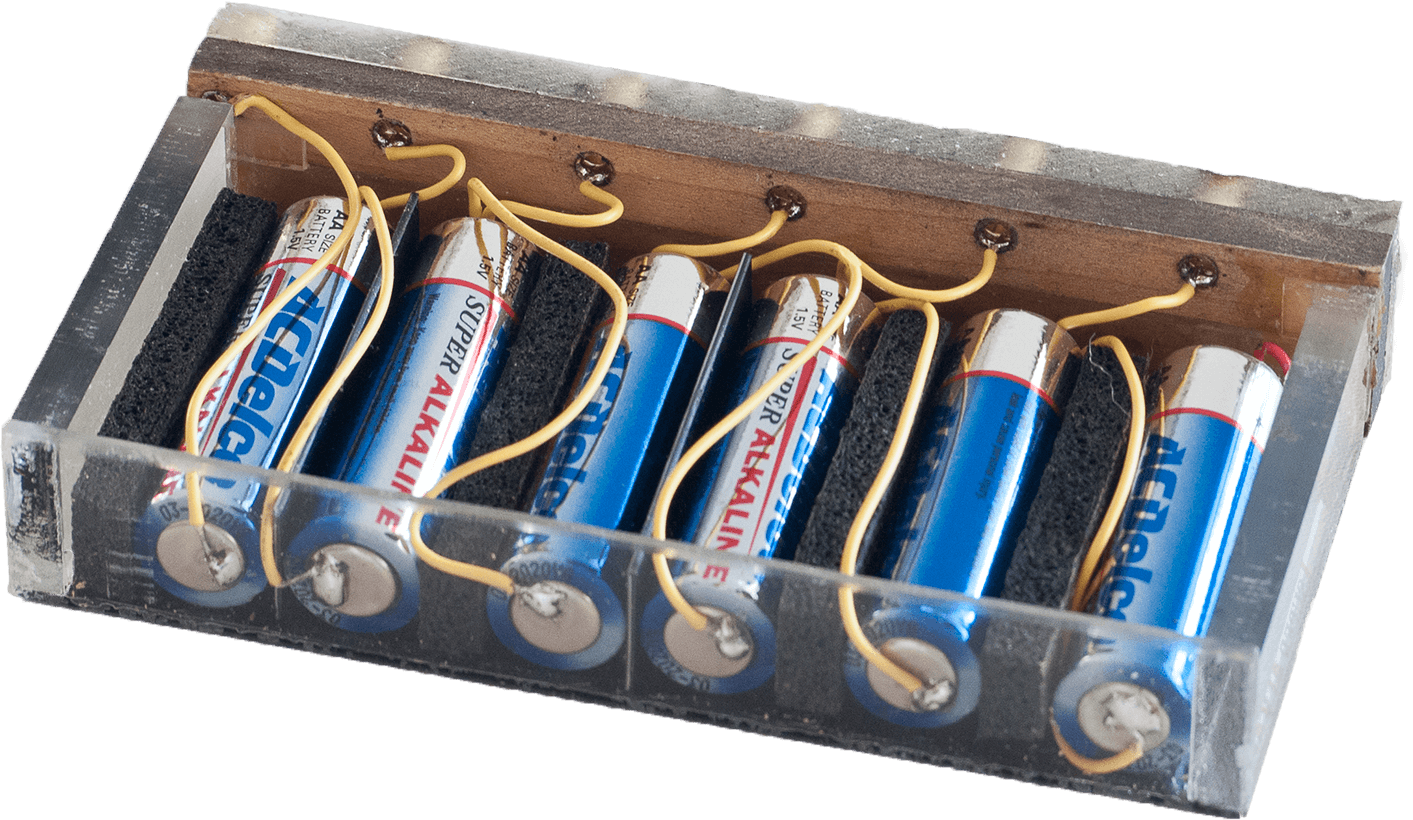
Once you have the wiring completed, check that you have approximately 9 volts in 1.5 volt steps. (The cells I used averaged 1.61 volts when fresh so expect some slight variation.) Now is a good time to do a dry run at assembling the connector strip to the battery box. Make sure that all the parts fit snugly together and are easy to align. Finally, roughen up the top of the plastic box to encourage a good surface for the contact cement (that smelly stuff you use to stick vinyl tiles to the floor or wood/melamine veneer to wood) to key to. Once you’re comfortable with the assembly, then solder the short wires to the blob of solder on each contact on the connector strip.
Apply the contact cement to the underside of the connector strip and to the top ends of the plastic box, making sure to keep the two sub-assemblies apart. Once the cement on the parts is touch dry, press them together firmly, making sure that they are correctly aligned. I tried using double sided sticky tape instead of contact cement, but it didn’t seem to provide as strong a bond as the contact cement.
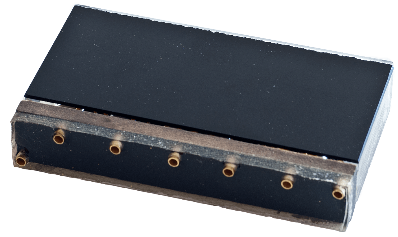
You now have the ‘innards’ of the battery complete! Congratulations! The height of the battery should be approximately 2.85”.
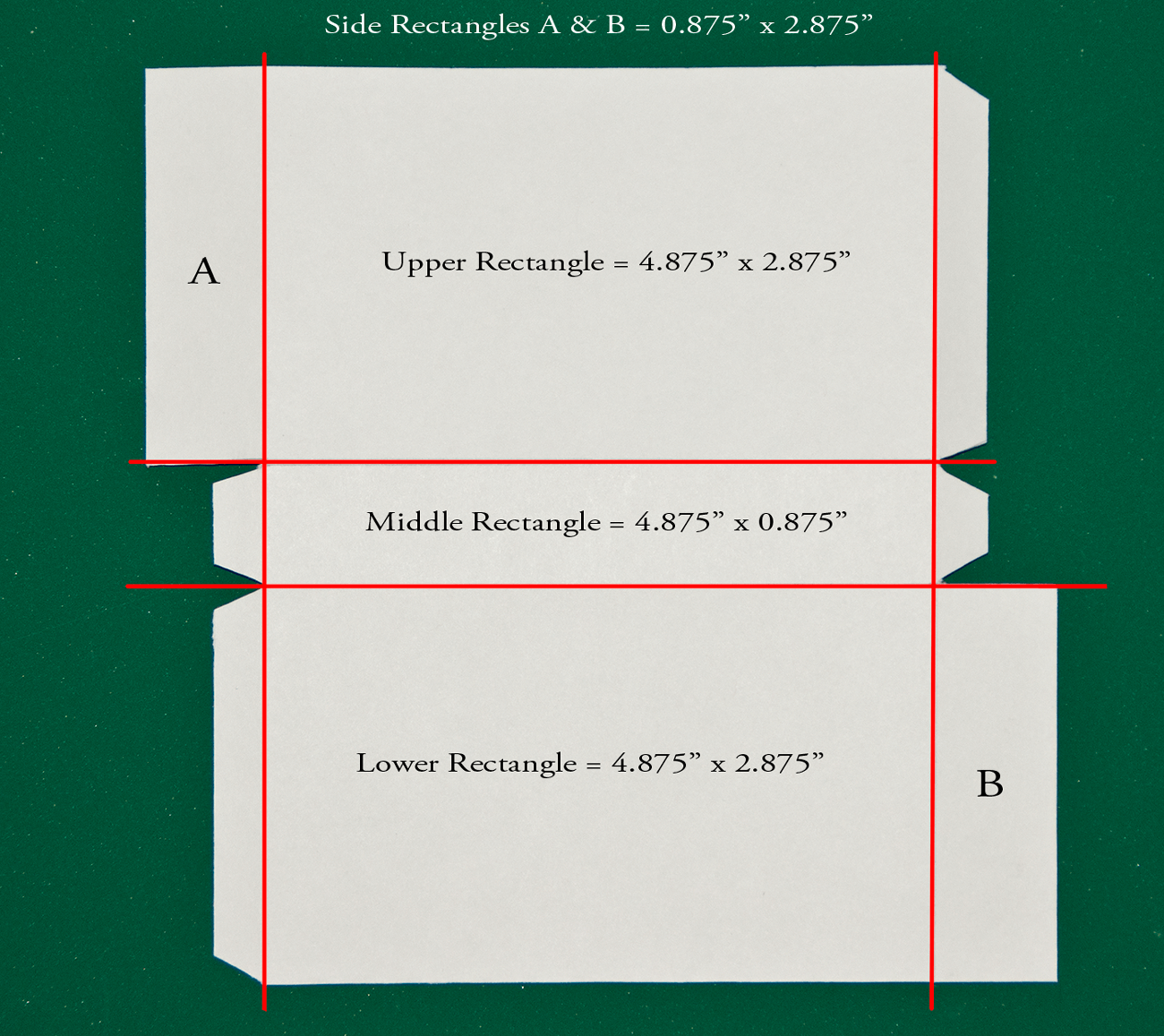
Paper/card container
I used 100 lb. weight card, which is approximately 0.01” (0.25 mm.) thick. The dimensions should be tailored to meet the size of the box you made, though the sketch below shows the nominal battery dimensions. On my first attempt, I made this container first and the plastic box afterwards – I don’t recommend that because I had quite a bit of trimming to do on the router table to make the box fit snugly! You can always fold some scrap paper around the battery box and use the fold dimensions for the card dimensions. Once you have the correct dimensions marked out, score the folds lightly and then cut the card. I used an Exacto knife and a steel rule. I used woodworker adhesive to glue the card container together as it’s nice and strong and you can use the actual battery box as a former and clamp the joints with whatever light clamps or rubber bands you have available.
Artwork
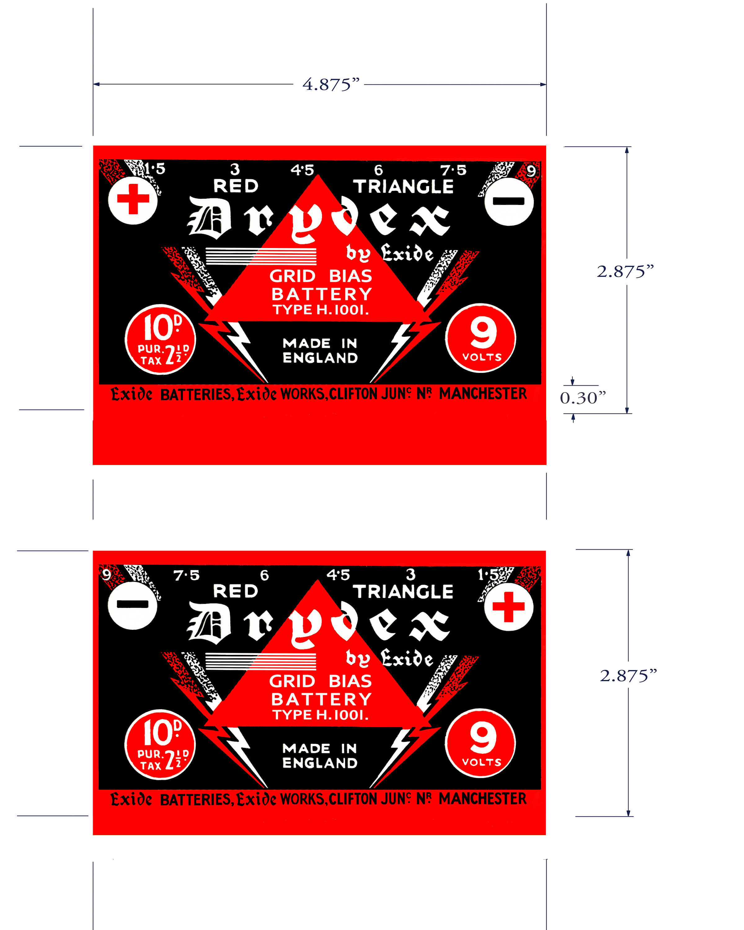
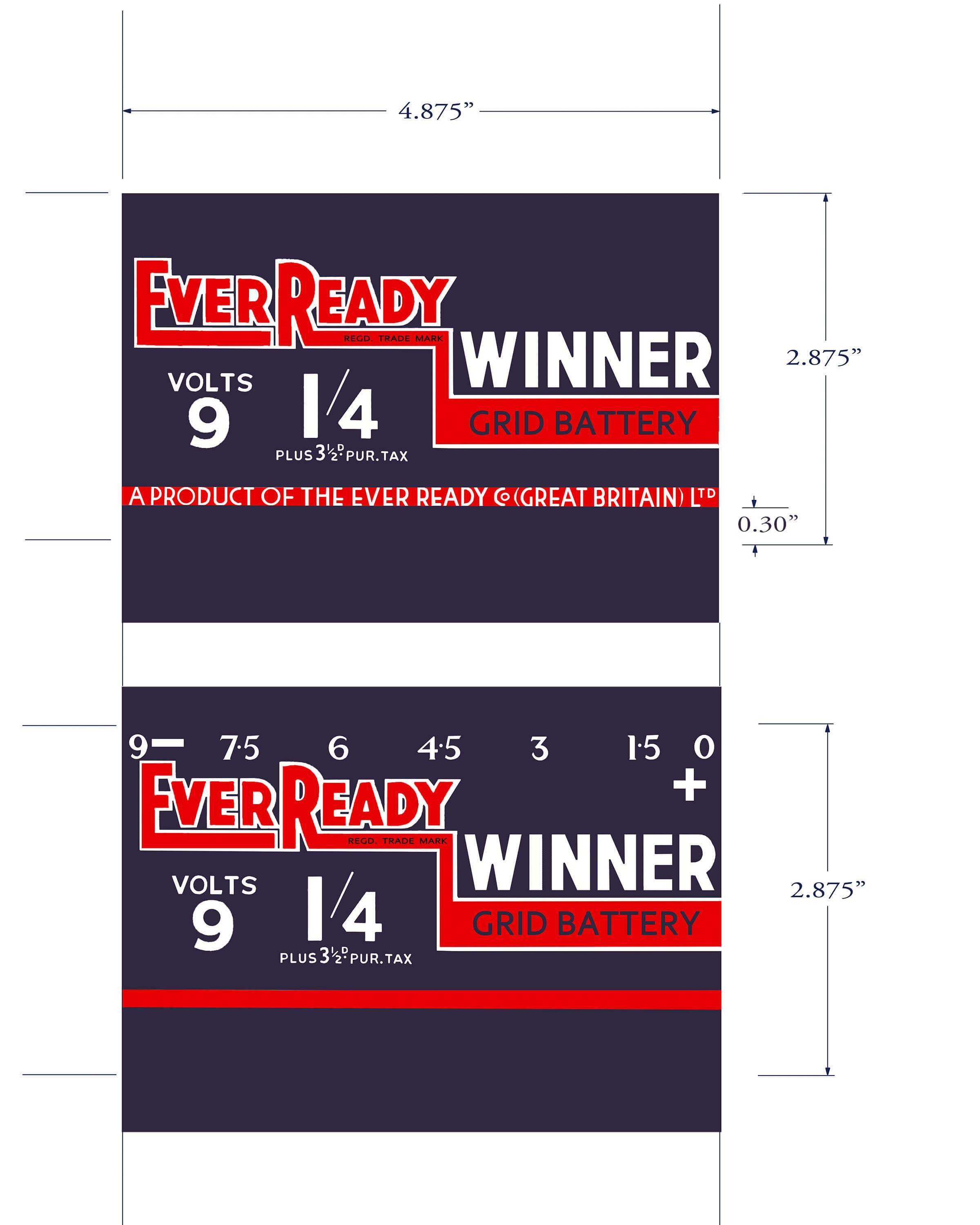
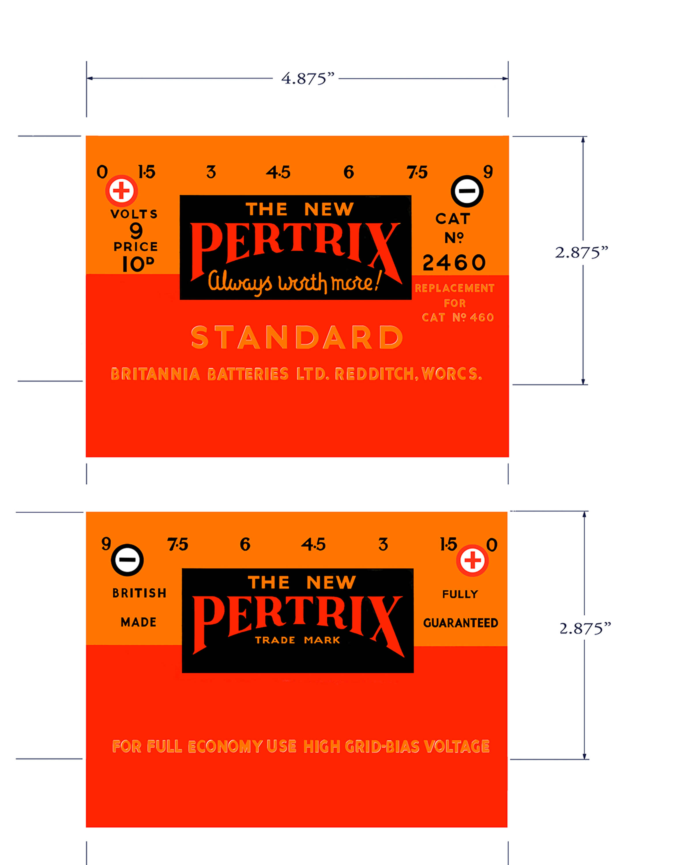
You can download the artwork for both batteries from the links at the end of this paragraph. The files should print nicely at 300 dpi on good inkjet paper. Initially, I tried printing directly on to the paper/card container described above, but the print bled into the card so that the overall printed dimensions were larger than the nominal 4.875 x 2.875 inches. Consequently, I recommend you to use good quality inkjet paper and don't be surprised if you have to print one or two copies to get the dimensions spot on. Print the end caps first and stick them on to the ends of the paper/card container. If they're slightly short, then just colour the edges of the container with a black Sharpie pen or whatever brand of permanent marker pen you use where you live. You should note that one side of the battery artwork is slightly 'longer' than the other side in order for it to wrap over the shorter one around the bottom of the battery. I used a glue stick to affix the artwork to the card, making sure that I glued both the artwork and the side of the paper/card container so that I could slide the artwork for good alignment. The end result should look very authentic.
To use the artwork below, right-click or command-click on an image, and save it to your disk.
Artwork for the Drydex battery
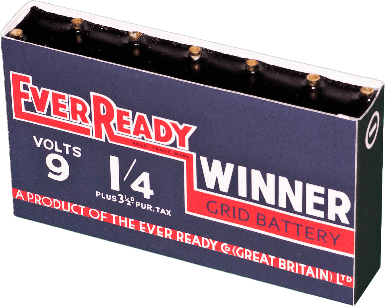
Artwork for the EverReady battery
Artwork for the Pertrix battery
Artwork for Drydex/EverReady end caps
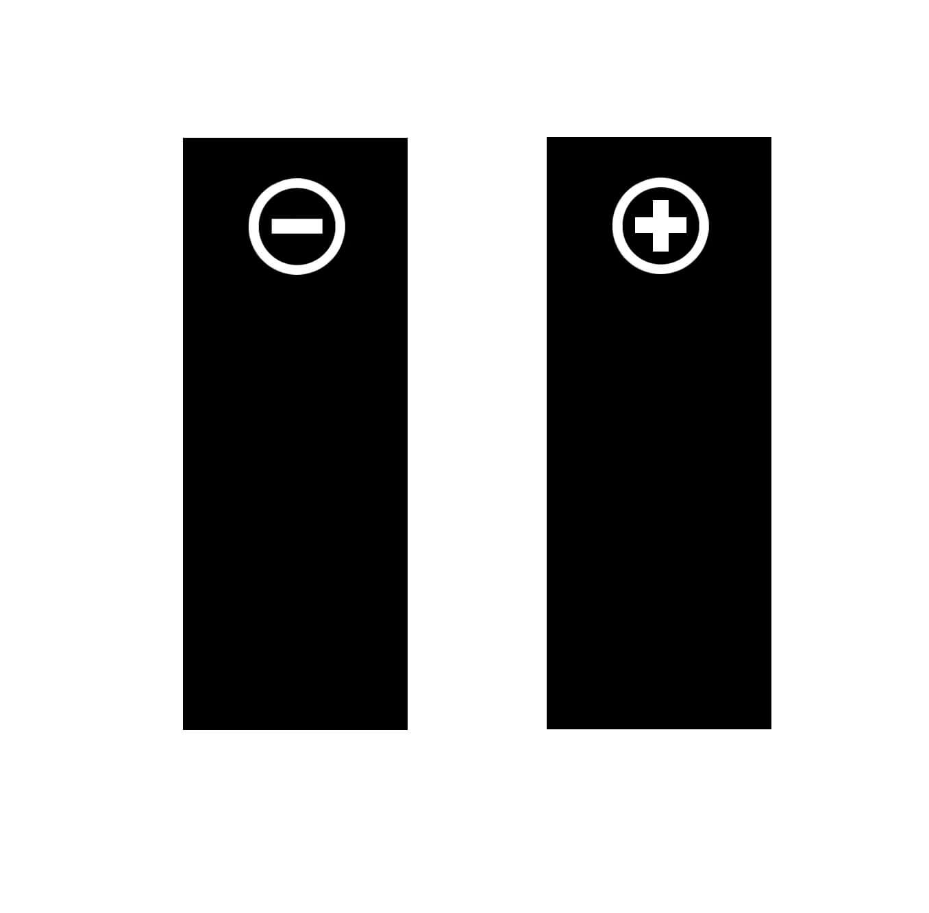
Artwork for Pertrix end caps

Summary
If everything went well, you should end up with a battery box as shown below and once fitted into the paper/card container, then you'll have a battery that looks better than the old original you started with. Give it a try - if I could do it, so can you!
If anyone has an interest in sharing scans of other grid bias batteries, please email me, since it would be good to have a few more designs from which to choose.