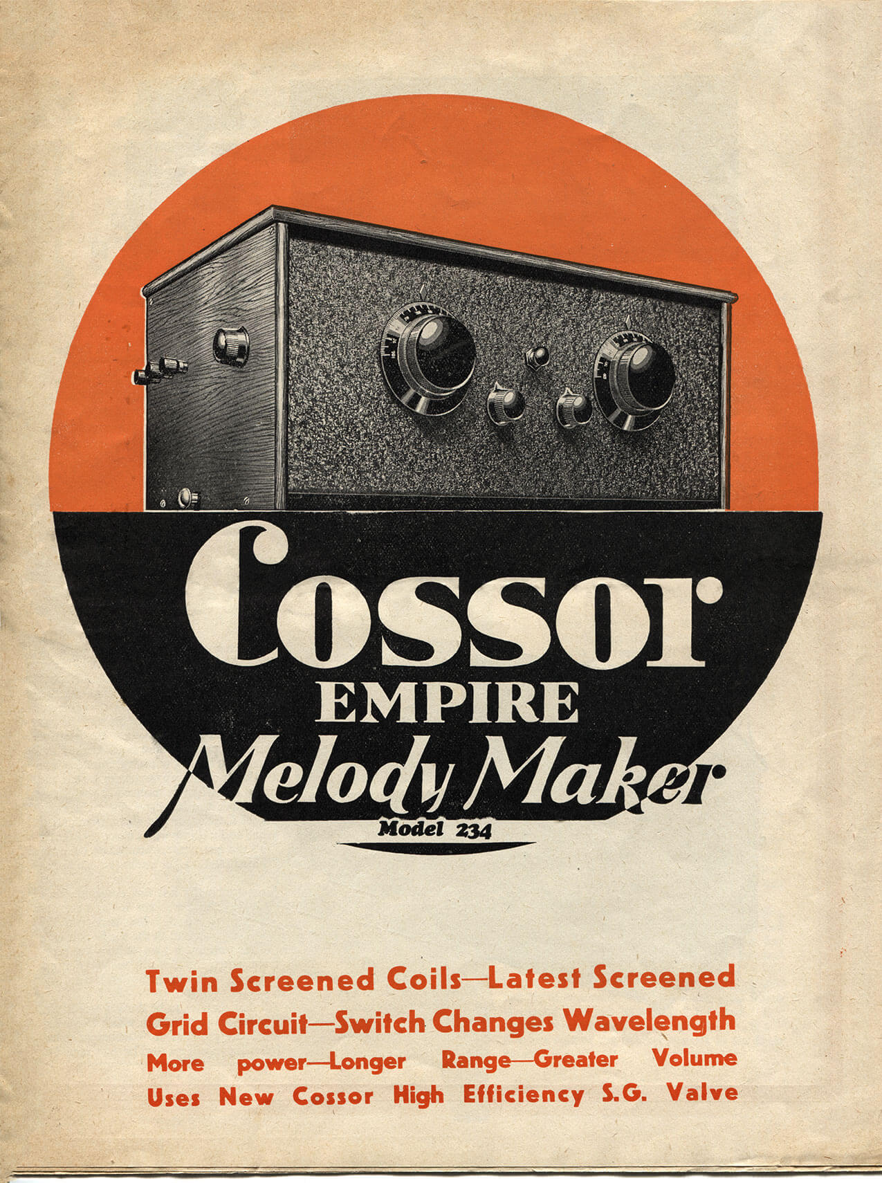
Cossor Empire Melody Maker (1931)
Introduction
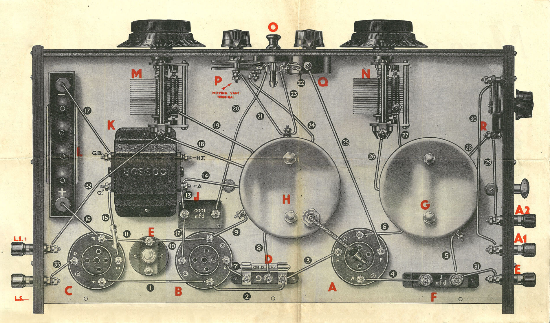
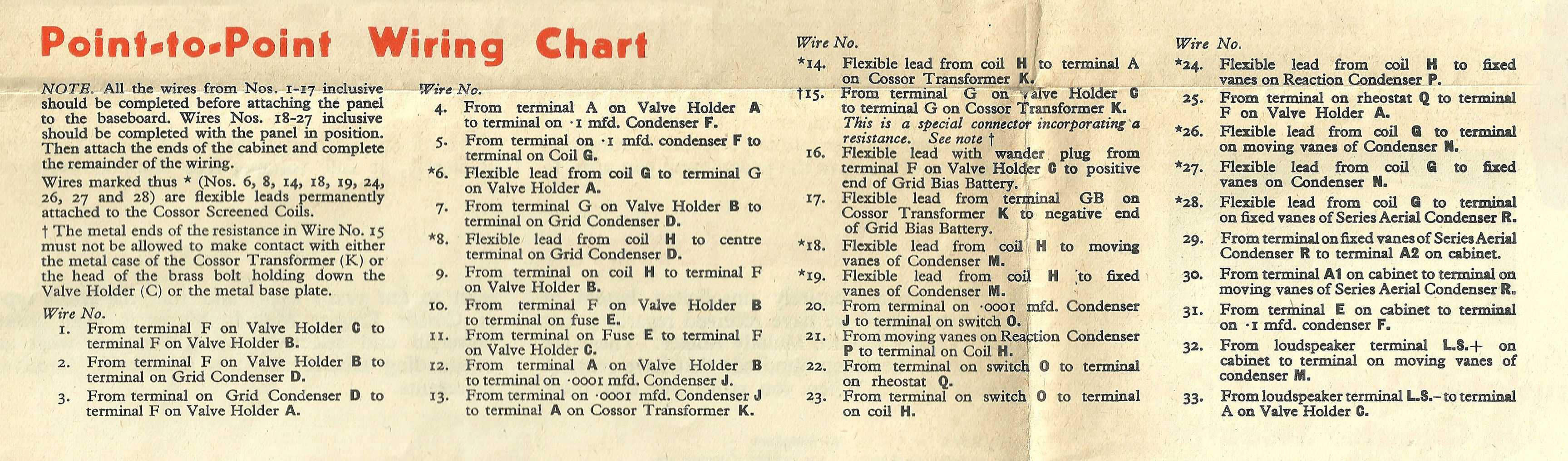
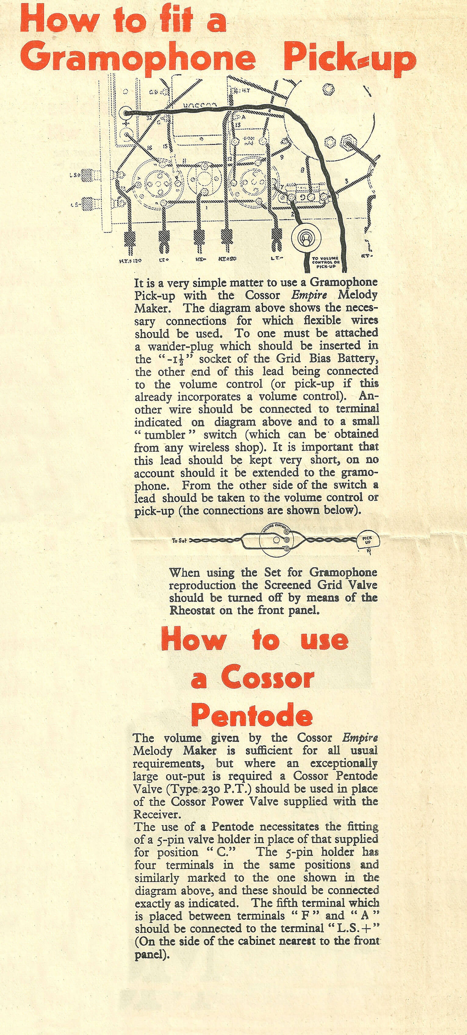
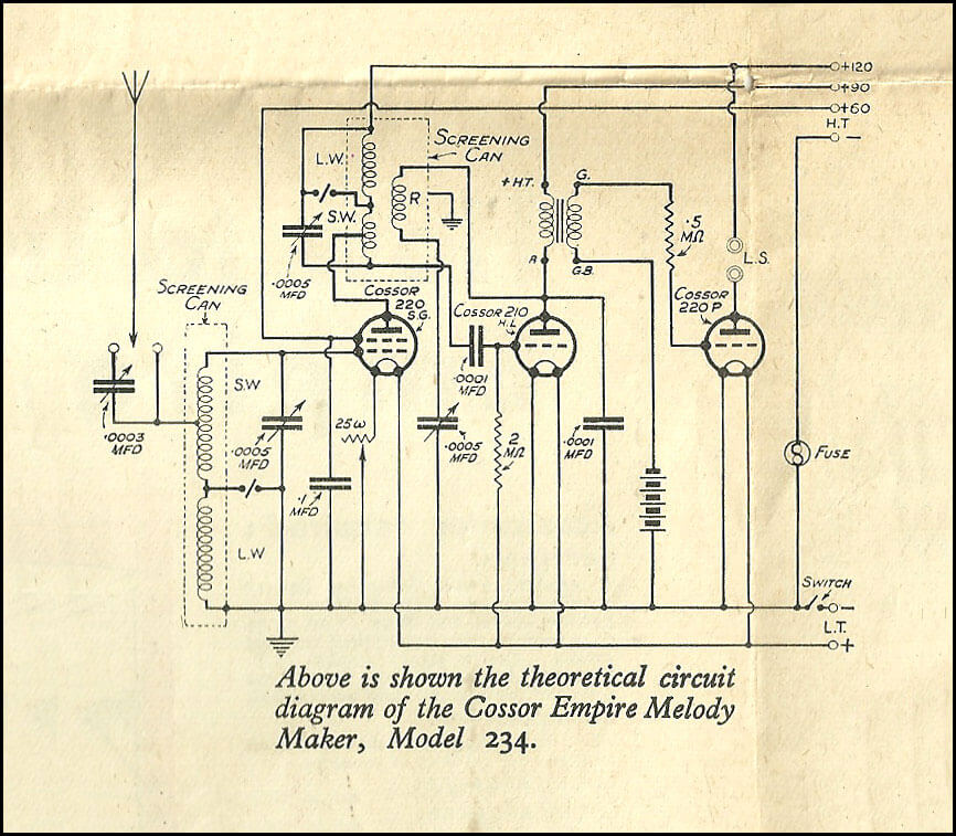
The Melody Maker Model 234 appears to have been perhaps the most popular of Cossor's kit radios, given that there seem to be more offered for sale today than for other models of that era. For all that, little original printed construction information comes to hand. So, it is hoped that the Cossor broadsheet set out below, supplied with each kit, will help enthusiasts who want to restore and return their sets to some semblance of their original condition since those sets that are offered for sale today are often in poor condition or have been modified over the years.

Restoration
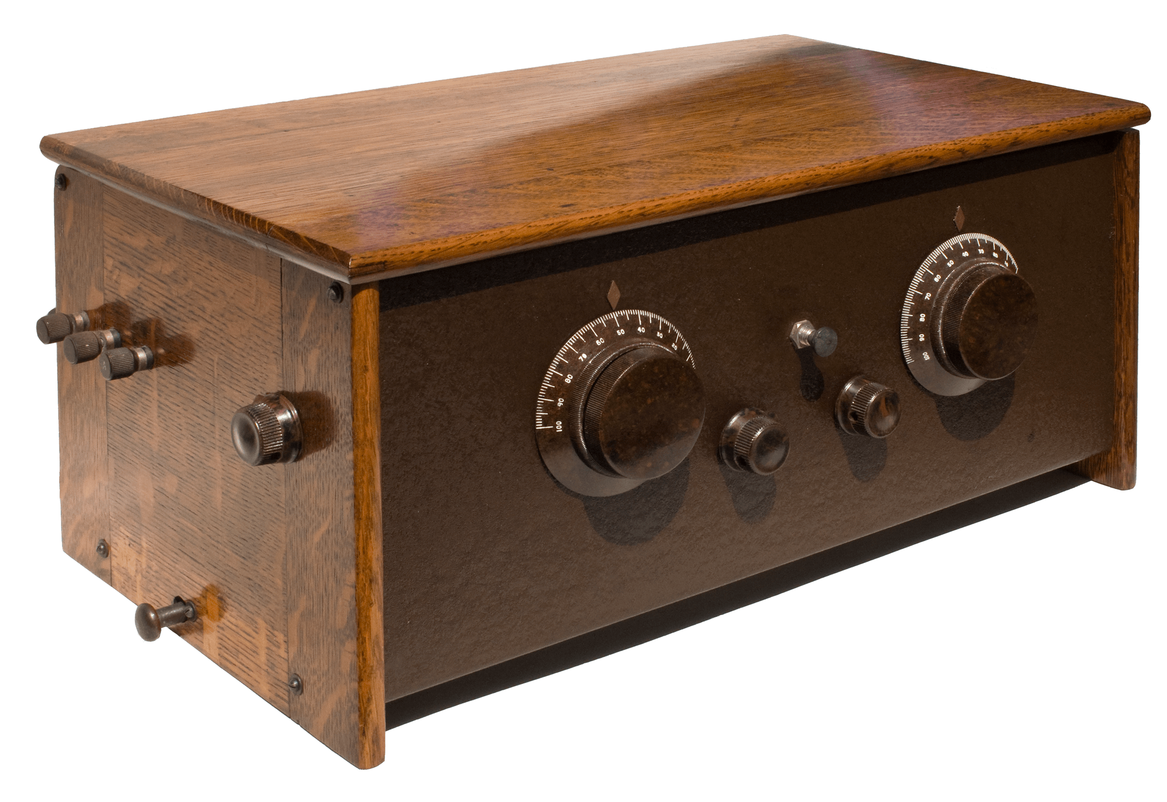
Much that the original information above allows us to search for correct or missing components and also confirms how the schematic information should be set out in the physical wiring, it gives no information about how to restore a shabby wooden cabinet or rusty base-plate. The radio pictured below has been in our family since the late nineteen-forties and had seen little light of day, let alone any use in that time. I remember one time as a youngster when my Dad had a go at powering it up with an equally shabby battery eliminator of the same period. In my Dad's words from his memory of the thirties, he used to say, "It takes half an hour to wire it up, half an hour to tune it in and then it only stays stable for half an hour." I have a vague memory that we managed to get something out of the radio, but not of any volume or quality. And so it remained for another thirty years. The varnish had deteriorated on the lid and wooden ends and there was a characteristic flower pot mark in the centre of the lid along with numerous scratches and nicks both inside and out. I could try to kid myself that preserving this 'original patina' was the way to go, but truthfully the radio looked ready for throwing away. To begin with, I sanded down the lid and was happy that it wasn't warped, twisted or cracked over the years. If any of the latter, then I would likely have fashioned a new one along with new end pieces, since it's very difficult to match new wood with old. I used 100 grit paper in an orbital sander to sand out the nicks and scratches, then progressed to 150/200 grit through to 400 for finishing. Afterwards, I used 400 grit in an old cork sanding block always sanding in the direction of the grain to avoid any minor swirls. I used the same treatment on both end pieces. My intention after the sanding was to finish the job with French polish rather than a modern polyurethane varnish. However, I'd never attempted French polishing before, so I practised using spare pieces of wood with varying degrees of success. The good thing is that it's fairly easy to remove any blotchy coats with alcohol as long as you move quickly. I used garnet coloured shellac flakes dissolved in denatured alcohol rather than buying ready mixed shellac since you can adjust the thickness of the mixture to your own work rate. I found that a fairly dilute mixture suited me, but it does mean that you have to apply many more coats. There are several online tutorials about French polishing and I encourage you to try it since the result enriches both the grain and colour of the old wood. Incidentally, those tutorials mention that you may need to use a special transparent filler to fill any hungry grain in the wood, but I found that old oak that's dried out over fifty years or more sands down remarkably well, especially if you do a really thorough final sanding with 400 grit sandpaper. Don't cut corners on the finishing phase of the sanding. The cabinet below shows what the garnet coloured shellac can do for enhancing the finish of old wood and also give it an authentic look.
Now to the metal surfaces. Cossor was seemingly very proud of that crinkle finish that would blend in so nicely with living room furnishings of the nineteen-thirties, but I have to admit that the finish of the front panel on this radio left an awful lot to be desired. Any trace of lustre had faded decades before and what was left was just a pastel/matte finish. First, degrease the metal panels with alcohol and don't be disconcerted if the finish looks even worse afterwards. If the old finish is just faded as mine was, but isn't scratched, worn away in any place, or marked with some aging station name, then I've found that a wipe-on polyurethane varnish works wonders on the front panel and is very forgiving in its application. I used a clear satin finish varnish (Minwax or similar), which returned the front panel to its original glister. Again, use several thin coats applied with a small pad made from an old cotton t-shirt or something similar. You'll be utterly amazed how the colour saturation returns, too, just because the fading had destroyed any hope of light reflections. If the front panel is too marked, rusty or otherwise marked, then you'll likely have to spray it with a matching (or close) coloured paint. Beware that anything other than a light spray will tend to mar the crinkle finish. My preference is for a light spray to cover any marks and then use the wipe-on varnish for protection and lustre.
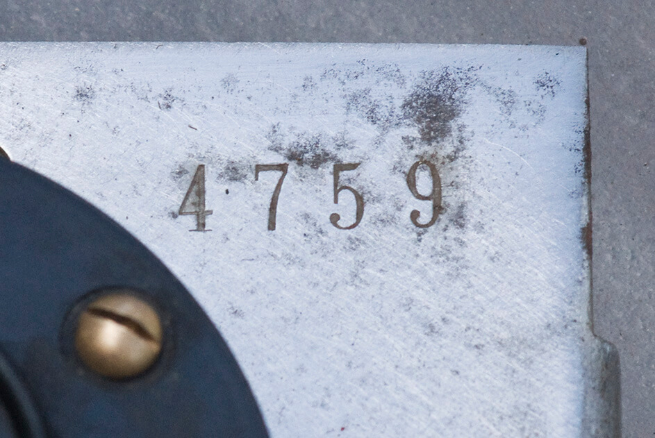
The base-plate on my radio was rusty in places, especially on the underside, and badly discoloured and indented where a grid bias battery had corroded in place at some former time. My decision was to strip down the radio after photographing it from several angles so that I knew how to put all the parts back together. Now, of course, you'll have all that information from the kit instructions here, so no need for photography! I just used wet/dry emery paper with plenty of water and frequent wiping with a cloth to see how things were going. I'm sure there are better and cleaner ways to clean up sheet steel, but I wasn't about to try any acid washes or other chemical treatment. Hand sanding took a while, but anything you do for these devices is a labour of love, so just take your time. A pleasant discovery was the serial/batch number in the rear right hand corner. Perhaps it's the part number of the base-plate, so I'd be interested in hearing from others whether your radio has that same number. If not, then it's likely to be the serial/batch number. Cleaning up the base-plate was all I did to it as rusting indoors is not a problem where I now live.
Once the woodwork and panels were restored, the control knobs looked terrible! Some of the graduated markings on the two tuning knobs were missing and this proved to be difficult to address. As with all other tasks described here, first I cleaned any grime out of the milled/knurled edges of the knobs with several wooden toothpicks as they don't scratch.. I tried chalk, chinagraph/grease pencil, crayon, etc., but none of these proved durable even after varnishing. In fact, the varnish typically 'pulled out' whatever whitening medium I had used. I resorted to some typing white-out paint, but I didn't have much luck with that either. Finally, and very warily, I used some touch-up paint that I'd bought for my Honda car. It worked far better than anything else that I'd tried and was easy to wipe off with a pad wetted with white spirit. Once the paint was well dried, I removed any smears left from the white spirit or paint with chrome polish. Yes, it was a bit scary, but you can see from the photo that the results look very presentable.
Electrically, the restoration was relatively easy since the circuitry is so simple. First, I checked the LF transformer. The primary winding (+HT to A) measured 4.2 kΩ while the secondary one (G to GB) was 1.43 kΩ. I also checked for any short circuits to ground. All checks were done using a DVM.
You'll probably find that the grid leak resistor is far from 2 MΩ (likely much higher), but it's easy to place a 1/10 watt resistor under the glass one. The same is true for the 0.5 MΩ resistor between the LF transformer and the grid to the output valve.
The mica capacitors seem to retain their nominal capacitance within reason, but you may find that the 0.1 uF capacitor decoupling the screen grid supply is way off value. Again, it's relatively easy to melt the pitch out of the old capacitor and install a modern replacement, but make sure that it's rated at 150 volts or higher.
Other components to check are the two main tuning capacitors. Make sure that the insulated bushes between the front panel and the capacitor shafts really are insulating each capacitor. Another check is to make sure that the moving vanes are not misaligned causing shorts. This can happen with rough handling over the years or if the radio has been badly stored. Fortunately, there is adequate leeway to align the vanes with the threaded supports for the fixed vanes and also the bearing adjustments for the moving ones.
One problem I still have with my radio is that the wavechange switch is just an actuator for two toggle switches at the base of each coil assembly. These switches are not ideal for their task and can easily become intermittent even with using judicious amounts of contact cleaner. Such switches are not easily replaceable these days, so you may have to do the same as me and live with this issue.
The other problem I had was with the insulation on the coil wiring for each coil. The rubber insulation hardens and cracks over the years and this can be an issue where the wires protrude through the screening cans. I slipped some heat shrink tubing on to the wires at each aperture where the wires come out through the screening cans. It doesn't look particularly good and I need to find a more elegant solution one day. The other wiring problem I had was that of the anode coil (F.C. 1110) to the armoured cable that attaches to the top cap of the screen grid valve. This had broken somewhere inside the armoured screen, so I replaced it with a piece of RG 213 coax that I had to hand. It fit conveniently inside the helical flexible armour so that I wouldn't end up with a kink in the aluminium helix. It's a fiddly job, but worth doing. Finally, check that all the wires are tightly screwed down at each end. If the valves are in reasonable condition, you should be ready to try out the set.
The set works remarkably well if the valves have good emission. Given that the valves have directly heated cathodes (filaments), make sure that your filament supply does not have any hum on the line or it will be amplified and cause all sorts of audio problems. A single gel cell makes a superb source, of course, nicely replacing the original 2 volt accumulator, but I use a mains powered supply equipped with a 317 regulator. As long as the transformer is capable of supplying upwards of an amp at greater than six volts, then the supply will be hum free since the three valves are rated at 0.2, 0.1 and 0.2 amps respectively. (Cossor's three digit code ascribes the first digit to the filament voltage and the second two to the filament current, so a 220 SG valve is rated at 200 mA filament current, whereas the 215 SG is rated at 150 mA.)
As far as the aerial is concerned, you don't need a really long wire. Three or four metres of wire provides a good signal for several local stations and it can be tuned using the small capacitor on the side of the set. I've found that a separate earth is not required these days, but if there's any hum you may find that it helps to reduce it. I tend to use a frame aerial made from ten turns of 26 gauge insulated wire wound on a square plastic frame about 0.5 metres on each side. Connecting this to the aerial and earth terminals brings in a good dozen stations easily during daylight hours and I find that the magnetic component of the signal is less susceptible to modern digital interference sources. The frame aerial also adds to selectivity as it is quite directional.
As far as HT voltages are concerned, I typically run the screen grid at 90 volts and the detector anode at sixty volts or less. I find that running the detector at a lower anode voltage results in better reaction control of oscillation. I use a home made grid bias battery, the details of which you can find on this site, and I find that -4.5 or -6 volts is just about right to give good audio with little (well, reasonable) distortion. In terms of loudspeakers, I've used a really old BTH C2 horn loudspeaker, a Celestion C12 balanced armature / reed loudspeaker, but I prefer a moving coil one driven through a standard output transformer.
I intend to amend this text with some more information for using the set with a 'dud' detector valve. I've found that a 1AD4 (DF62) valve with a single diode in series with its filament works well as a detector valve if you can hide the assembly under the valve base. With the New Cossor Melody Maker, it was easy to mill/rout out a depression in the wooden baseboard under the detector valve, but with this set one needs a couple of spacers to raise the valve base just enough to position the miniature valve and diode underneath. The 'dud' valve can then just sit above in the valve holder and nobody is any the wiser! So, watch this space from time to time for details and photographs.